Standard sewage network for refugee camps
Project made by: Mona El Kass, with help of university group: Sara Trad, Louay Jarkass, Ali El Rez, Ihab Nashabeh, Abdul Aziz Jbara, and with a supervision from Dr. Mohamed ElKholy.
Introduction:
The aim of this project is to design a simple standard sewage network that could be used in any camp around the world, and the conclusion was to designing a sewage network for 2 standard camps layout.
Designing a sewage network is to size all the pipes based on the available diameters in the market and according to their materials, and to check that the slopes and the flow velocities are within the acceptable ranges.
A tour of the Syrian refugee in the North of Lebanon was made in the beginning to know their sanitation problems and to try to find a solution.
Literature Review:
The Syrian refugee camps in Lebanon have in total 10086 refugees distributed in 4 regions as shown in Fig.1 and the LEB Relief association has provided 1929 tents for them.

Zaatari Camp Design:

Figure 2: Camp tents groups, roads, and pipes drawing on AutoCAD.

Figure 3: Plan view of the main pipes of Zaatari camp.
The software will give the elevation profiles for each pipe to see and understand all the design results.

Circular Standard Camp Design:
The first layout is the circular one:

Figure 5: Plan view of the circular camp layout.

Figure 6: Tents distribution.
In each group of tents, we have:
8+10+12+14+16+18+20+22+24+26= 170 tents (see figure 6).
There
are 10 parts so a total of 170*10 = 1700 tents in the camp (see figure 5 ).
1700*6 persons in each tent = 10 200 persons in the camp.

Figure 7: Rectangular tent design.
Figure 7, shows
the rectangular tent design that is easy to use and that is available for 6
persons.

Figure 8: Manholes and pipes.
Design steps:
o
Draw the main pipes as polylines using AutoCAD, and at
each manhole, begin a new polyline.
o
Open a new file in the Sewer GEMS,
user data extension, then right-click on conduit, and add a new field with the name
“cad” for example.
o
Import the cad file containing the
main pipes as DXF file, in the Sewer GEMS, by clicking on “Model Builder”
o
Change the units to “m” and
establish connectivity using spatial data with a tolerance of 1 m.
o
Table type is a conduit, Key fields are
labeled then, select the field layer and choose “cad” as property.
o
We will obtain a plan containing the
main pipes with a manhole at each new polyline (Fig 8).
o
Select the outlet point and make it
an outfall.
o
Make an excel sheet to find the
sanitary load at each manhole.
o
Change the size of the Manholes to
be larger, by clicking on manhole, label, and change the height multiplier.
o
Click on conduit catalog and add
define 4 different conduit diameters of PVC material: inside diameter of 300,
200, 50, and 100 mm. Manning’s coefficient = 0.013 and Hazen Williams
coefficient = 130.The material is PVC.
The diameters are small when dealing with camps (not buildings with
so many floors).
o
Click on unit sanitary load, and add
the unit sanitary load = 30 L/Person/day in the camp.
o
Select Design constraints, and
modify the default design constraints for the velocity to be between 0.6 and
0.9 m/s, the % full to be 85 %, the cover to be between 0 and 2 m, and the piping
matching to be at the crowns.
o
Then modify the slopes: Set the
maximum slope = 0.01, and the minimum slope varies according to the rise: for a
rise = 50 mm → slope = 0.01, rise = 100 mm → slope = 0.008, rise = 150 mm →
slope = 0.004, rise = 200 mm → slope = 0.003.
o
Click on extreme flows, then add the
values of the constants in Babbitt equation: Population unit is Capita * 103,
c1 = c3 = m1 =0, c2 = 5, e1 = m2 = 1 and e2 = 0.2.
o
Select the manholes, and select the
unit sanitary dry weather load, loading unit count = 0.
o
Add in the loading unit conduit
column, the values calculated in the excel file for each manhole.
o
Flex table manhole, set ground
elevation = 0.5 m to have different levels of rim and invert elevation.
o
Click on “Options” to modify the
base calculation options. Select the calculation type Design, and select false
in the case of use pumped flow.
o
Click on compute. Try to not have
any errors and any warnings.
If you have a warning, the Sewer GEMS will compute and give answers
but it will not if you have any error.
o
In the results Flex conduit table, the diameters of the pipes are 50 in the beginning of the pipe where the flow is
small, then the diameter increases to 100 mm in some regions near the outfall
where the largest flow.

o
Click on view, profiles, new, and
select the profiles needed (Fig.9).
o
Select view, profiles, and double
click on each profile to obtain the elevations at each station, or right-click,
view engineering profile to obtain a detailed drawing of the pipes (Fig. 10).

o
The Sewer GEM software will do the
design of the network and find the profile of the elevation of the pipes, the
diameter, length and depth of excavation, and of fill needed for each pipe, in
addition to the flow capacity.
The second layout is the hexagonal one (Fig. 11):

The unit
sanitary load is 30 L/d for 1 capita, in the 2 layouts. Use the same design
steps.

The Sewer GEM software will do the design of the network and find
the profile of the elevation of the pipes (Fig. 13), the diameter,
length and depth of excavation, and of fill needed for each pipe, in addition to
the flow capacity.

In this layout, we used the circular tent design that contains 5 persons (Fig 14 and 15).


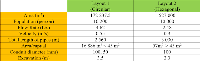
Comparison between the two models designs:


Conclusion:
The proposed layouts for drainage
networks would be perfect in refugees’ camps. These camps can accommodate more
than ten thousand refugees in addition to many other service facilities. The
design of these camps followed the global standardization set by the United
Nation and by other design standards and guidelines. In the design, the slopes
of the drainage pipes and the velocity constraints are selected in a way to
have minimum excavation depths and to have the flow velocity within its design
ranges.
Discussion of the project:
https://news.ycombinator.com/item?id=24525765#24534845
Comments
Post a Comment